Sunday, 23 July 2023

6 bit × 10 bit multiply

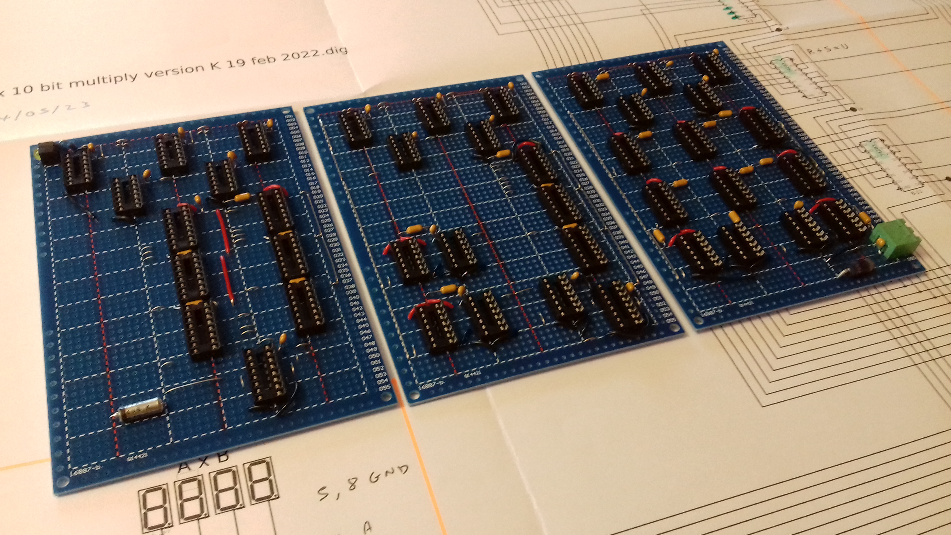
From 31st May 2023 - IC sockets, decoupling capacitors...


to 22nd July 2023...


Here we have 39 × 2CC = 9F6C. The thing almost worked first time - but one of the 74283s had got inserted without its pin 1 (it was inadvertently bent away from the socket)...giving obviously wrong results like 3F × 000 = 0200. Incredibly (given the mess of wiring), that was the only issue.

Saturday, 17 June 2023

3 bit × 10 bit multiply

 Probably the second easiest bit of circuitry...


Here we have 7 × 3FF = 1BF9.


Here we have 3 × 61 = 0123.


Sunday, 11 June 2023

6 bit ÷ ten (decimal) revisited

Hand soldering of the IDC connectors is proving too fiddly (when constructing the 3 bit × 10 bit multiplier board - see next post), so I've opted to use D-sub connectors, fixed to an aluminium cross piece:


The D-subs are fixed to the cross piece using Richco, PCB MB 01 mounting blocks and M3 self tappers. The cross piece is fixed to the rail pieces using Richco HTSB M3-9-5-2 9 mm threaded standoffs. 


I like this approach - looking mainframe-esque:


Sunday, 30 April 2023

First hardware: 6 bit ÷ ten (decimal)

First attempt, on a 220 mm × 100 mm (ROTH ELEKTRONIK - RE310-S2) - appropriately named LABOR CARD, ended in early abandonment; it was becoming way too cramped.

So, my new approach is to use 3 off (or, for some boards, 4 off) 100 mm × 150 mm boards (FR4), assembled into a 'tray'. Two 10 mm × 10 mm × 1 mm aluminium angles form the tray; the boards are attached via nylon PCB mounting blocks (Richco: PCB MB 01) and 3/4 inch M3 (No. 4) self tappers:


The aluminium rails will help when it comes to a final assembly of the thing - it's anticipated that they will slide into some type of card guide, so that several trays can be stacked up. Probably something like 27 trays in total.

And so we have:


Board power (5 V) comes in bottom right; power indicator top left. There's a 6u8 (35V!) solid tantalum capacitor, plus 100 nF ceramics next to each chip. Data in/out via IDC connectors.

I simply love the old TIL 311 hexadecimal displays (although they draw something crazy like 90 mA each!). 

And here have 3F ÷ A = 6, remainder 3. Amazingly, this all worked first time!

Total current consumption is 420 mA max - depending on what's displayed. If/when I get the whole thing working, I can pull the display chips - they wouldn't be readable anyway, when the boards are stacked up - included for the moment for test purposes.

All the chips are LS, except for the 7425 (dual 4-input NOR), which is the basic Texas SN7425N; I couldn't find the LS version of this one.


Saturday, 26 November 2022

An exception

I have found one case where the TLC algorithm does not give the 'expected' result. By 'expected' I mean the value given by

The exception occurs when operator ⊡ is equal to PLUS, i.e. the ALU(9,1) case, and γ = 1. The expected result is

However, the TLC algorithm yields something different, for example:

The algorithm yields rational values, which are close to the expected 1/α value.

It's conjectured that, for the ALU(9,1) with γ = 1 case, the actual value given by the algorithm is given by
where b is a parameter in the TLC algorithm (see post of 18th December 2021). Hence, 
It is evident that the larger the value of b, the closer the algorithm's value is to the expected 1/α value. A value of b = 888 was used for the above.

The rational value and that produced by the algorithm agree to large numbers of digits. For example, for the α = 2 example (i.e. 219780/439561), the rational value and the algorithm's value agree to at least 5000 digits; this may reflect the fact that the value is a repeating decimal (period 525).

Finally, we look at the effect that parameter b has on the calculation of  π:


There's a little blip at b = 888; this gives 265 correct decimal places. That's actually two more correct digits than given in the 25th September 2021 post; that result took b = 1023.


Hence there appears to be an optimum value of b - at least for the π calculation.  The TTL implementation allows the user to set b to any particular value.

As mentioned in a previous post, the actual values produced by the TTL implementation may differ from that produced by the above expressions for P and Q, due to the fact that the TTL implementation necessarily uses limited bit widths.


Friday, 25 November 2022

First discovery

Previously, it was mentioned that setting ALPHA = 1, GAMMA = 1, BETA = 10 and omitting the d = d * b operation (OP#1) (as for the calculation of e), and using the exclusive or operation, yields

1.543080634815243778477905620757061682601529112365863704737402...

which happens to be cosh(1).

Hence we state the interesting identity:

where ⊕ means exclusive or, and we replace 1 ⊕ 1 = 0 with 1 (to avoid dividing by zero).

The product in the denominator gives 1, 3, 6, 30, 120, 840, 5040... which is A265376 in the The On-Line Encyclopedia of Integer Sequences (OEIS), Published electronically at http://oeis.org. The proof that the above identity is true is straightforward: even terms of the denominator equal (2n-1)! + (2n)! and odd terms equal (2n-1)!. The former sum to 1/e and the latter to sinh(1), and we recall cosh(1) = 1/e + sinh(1).

And there's plenty more of this type of thing, for example (i.e. setting ALPHA = 4, GAMMA = 4, BETA = 10) gives the following:

Although there might seem to be a preponderance for the exclusive or operation to yield values writable in terms of hyperbolic functions, this is not always the case, for example:


Beautiful methods of reckoning

After a bit of thought, I've managed to come up with two expressions that define exactly what it is that the TLC algorithm (described earlier) computes.

For a given ALPHA, BETA and GAMMA, the algorithm computes one of the following two quantities. P if the d = d * b operation (OP#1) is included, and Q if it is omitted.

In the above, the ⊡ symbol means an arithmetic/logical operator; for the TLC project it's one of those implemented by the 74181 arithmetic logic unit, as listed in the previous post. To avoid division by zero, instances for which γk ⊡ α = 0 are replaced with unity.

(Numerical experiments suggest that the above expressions work for all the arithmetic/logical operations supported by the 74181 as listed in the previous post. An obvious (unanswered) question is this: what other operations does the algorithm work for?)

So, for example, for the π calculation operator ⊡ is A MINUS B (i.e. ALU row 6, column 2). And we set ALPHA = 1, BETA = 20 and GAMMA = 2, and thus compute the quantity given by

where operation OP#1 is included (i.e. in this mode the upper of the two equations is computed (P)). 

Omitting OP#1 (i.e. the lower of the two equations is computed (Q)), gives


where erf (x) is the error function. The first 2504 digits of the value produced by the TLC algorithm are correct. (This constant is mentioned in Finch, Mathematical Constants: 94 (Encyclopedia of Mathematics and its Applications), p. 423.)

Note: the TTL implementation of the TLC algorithm represents the algorithm's different variables using various limited numbers of bits - for example the d = d * b operation (OP#1) uses a 6 bit times 10 bit multiplier to yield a 15 bit result (bit 16 is ignored). This means that the actual value produced by the TTL implementation may differ from that produced by the above expressions for P and Q. This is not always the case, however - the algorithm produces 266 correct digits of π, with or without the TTL implementation's finite bit widths (with parameter b = 888).

On the other hand, ALU(9,1) (i.e. PLUS operation), with ALPHA = 1, BETA = 10, GAMMA = 1, and OP#1 enabled, yields

0.9989875126560917988525143... = 2960/2963 (no limitation on bit width)

and 

1.2202931302994487041321361... (TTL implementation).

As discussed in a later post (26th November), neither of these values agrees with the 'expected' result (unity).


Sunday, 20 November 2022

Something interesting

The value g = GAMMA * ± ALPHA is obtained using the three bit times ten bit multiplier (to give the GAMMA * b), and three 74181 arithmetic logic units to make the addition or subtraction.

But, the 74181 ALUs can do more than addition or subtraction...

Here, I've labelled up the rows and columns: discounting duplicates, there are some 38 different arithmetic/logic operations that are possible. The addition of six switches allows any of these different operations to be used:


Hence the thing calculates g = ALU(row,col,A,B), where row and col are the row and column as per the table above, and A = GAMMA * b and B = ALPHA.

So, we have g = ALU(6,2,A,B) = A MINUS B = GAMMA * b - ALPHA; if we set ALPHA = 1 and GAMMA = 2 (with BETA = 20) we get 3.14159265358979323846264338...

But how about something more exotic?

g = ALU(6,0,A,B) = A ⊕ B = GAMMA * b ⊕ ALPHA, where ⊕ is the exclusive or operation.

Setting ALPHA = 1, GAMMA = 1, BETA = 10 and omitting the d = d * b operation (OP#1) (as for the calculation of e), we get

1.543080634815243778477905620757061682601529112365863704737402...

which happens to be cosh(1). The first 2,236 digits of this result are correct. Discovering that this value is cosh(1) wasn't difficult: I just searched for '1.543080634815' on Google!

And there's a lot more of this type of thing...

...another example: ALPHA = 1, BETA = 5, GAMMA = 1, with ALU(1,2) = A | B = GAMMA * b | ALPHA, where | is logical or; operation (OP#1) (again, as for the calculation of e), we get

0.331224981744493362805940652824580844936569932976054216288429...

This equals I1(1) + I0(1) - 3/2 , where I1 and I0  are modified Bessel functions of the first kind. The result from the algorithm is correct to more than 2000 digits.

Showing that the above is indeed the sum of a couple of Bessel functions requires substantially more effort than typing a number into Google. More on this later.

Interestingly, it seems that perhaps all the 38 possible ALU configurations yield 'proper' values, some more 'interesting' than others; I'd naively assumed that the logic operations would not produce anything meaningful, but this appears not to be the case at all.


I'll end this post with another bizarre example:

ALPHA = 15, BETA = 10, GAMMA = 1, with ALU(11,0) = A & B = GAMMA * b & ALPHA, where & is logical and; operation (OP#1) (again, as for the calculation of e), we get

1.718281828461073178906616813933686139831054397588246567510596...

It looks like e - 1 = 1.71828..., but it isn't (the numbers differ at the eleventh decimal place).

Rather, the value appears to be equal to

2246953104077 / 1307674367999 

where, even more interestingly, the denominator equals (15! -1). The computed value (1.71828...) and the rational value agree to 672 digits.


Monday, 18 April 2022

GitHub

The complete set of schematics can be found here:

https://github.com/pac-mcnair/spigot-machine

(.dig (Digital) files, .svg files and PDFs)


Sunday, 27 February 2022

By omnibus I traveled to Brooklyn

Setting GAMMA = 1, BETA = 10, ALPHA = -1 and omitting the d = d * b operation (OP#1), the machine pops out:


...and so on. The first 2,232 digits are correct, as far as the 369. Then we get 975; the correct digits are 882.


The machine has a counter that displays the total number of triplets output - for the above, the count is 745 = 2235 digits have been output.


It's not that fast: the Digital simulation took about five hours(!) to get to triplet number 745. When the simulation's running, there's a little '3 kHz' at the bottom left of the Digital screen - not sure what this means/indicates...but it'll be interesting to see how fast/slow the actual circuitry is in practice. 


Saturday, 26 February 2022

Master loop

This is the top level circuitry, which implements the loop structure of the algorithm, and holds the various variables. It also deals with user control - i.e. the user can reset, run, pause etc the computation. And, there's the important matter of output. The top level circuitry makes use of the various previously-described sub-circuits:

    [master loop version Z 19 feb 2022.dig]

|
|
        |-----[3 x 10 bit multiply version E 19 feb 2022.dig] (purple)
|
|
        |-----[6 x 10 bit multiply version K 19 feb 2022.dig] (yellow)
|
|
        |-----[15 bit div 11 bit blocked version E 05 feb 2022.dig] (orange)
|      |
        |      |
        |      |-----[15 bit div 11 bit triple block version B 05 feb 2022.dig] (teal)
|
        |
        |-----[6 bit div ten version I 06 feb 2022.dig] (green)

The 15 bit div 11 bit circuit (posted November 2021) is unchanged, but had to be re-drawn - to make it readable when printed even on the biggest available paper size! The 15 bit div 11 bit 'blocked' version divides the original circuit into five stages, each of which is implemented as a '15 bit div 11 triple block' circuit (which contains nine 74181 ALUs). 

The complete master loop circuit is shown below - it's pretty much unreadable as it stands, so it's been divided into ten pieces.


The various pieces are interconnected with Digital 'tunnel elements'; in real life these will be interconnecting wires (ribbon cable?). Each of the ten pieces is a reasonable size (chip count) to go on a single board; so about ten boards for the master loop, plus three further boards, plus the 15 bit div 11 which is likely to be six boards in itself, giving something like 19 boards in total. I am thinking about 100 mm x 220 mm Eurocard types. 

Anyway, here's the output (appearing at the bottom right (block 10)) of the master loop circuit - the circuit displays eighteen digits at a time; the left-hand nine digits are:


and the right-hand nine digits are:


And, yes, that's a decimal point after the first digit. In operation, the digits pop out in groups of three, and the display scrolls across (with said decimal point). The user has the option of making the machine wait after it has output eighteen digits; pressing RESUME, starts the calculation of the next batch of 18 digits (the final triplet is shown also):


[I've also included some circuitry to interface to a 3-digit printer(!) - this allows a printer to tell the machine to wait, whilst it prints out the triplet of digits (perhaps some sort of wood block contraption printing onto a long roll of paper would be fun...)].

I'll put more detail of each of the ten pieces of the master loop circuit in the next few posts.


Chip count (master loop only - not sub-circuits)

        7400           7
        7402           1
        7404          13
        7405           1
        7407           1
        7408          16
        7410           2
        7411           7
        7420           1
        7427           4
        7432           4
        7442           1
        7454           3
        7474           2
        7477          18
        7485           1
       74132           1
       74138           1
       74154           2
       74160           8
       74161           8
       74173           2
       74181           7
       74182           2
       74191           3
       74214          11
       74245          16
       74247          22
       74260           2
       74273           6
       74283           4
       74367           1
       74373           3
       74541          10

plus LEDs for diagnostics, and for output of the eighteen digits of the number - at least at the moment. Maybe I'll go for a vacuum fluorescent display of Nixie tubes.

The total chip count (i.e. including all sub-circuits) stands at 358. Perhaps appropriately for a machine of this nature, the most numerous chip is the 74181 ALU (55 required); the next most popular is the 7408 quad 2-input AND (39), followed by the 74367 hex non-inverting buffer - to drive diagnostic LEDs (38).

Thinking ahead, I guess something like 20 - 30 amps might be needed...


Saturday, 18 December 2021

10 bit x 3 bit multiply

Here's the 10 bit x 3 bit multiply circuit - it's just a cut down version of the previously-posted 10 bit x 6 bit multiplier:


Chip count:

6 × 74283 (4-bit full adder)

8 × 7408 (quad AND gate)

plus LEDs for diagnostics.


Revised algorithm: small changes, big impact: Euler's number

I've revisited the spigot algorithm (posted 25th September 2021), and in the spirit of exploration, looked at what happens if:

(a)    d = d + 20 becomes d = d + BETA, where BETA is an integer;

(b)    g = 2 * b - 1 becomes g = GAMMA * b ± ALPHA, where GAMMA and ALPHA are integers;

(c)    d = d * b becomes optional.

These changes are interesting because they are easily implemented in the hardware, and enable numbers other than π to be computed. The first 'discovery' was:

ALPHA = 0, BETA = 10 and GAMMA = 1, with operation d = d * b omitted, which yields 🥁🥁🥁

1.718281828459045235360287471352662497757247093699959574966967627724076...

which is one less than Euler's number.

Or, how about ALPHA = -1, BETA = 10 and GAMMA = 1, with operation d = d * b omitted?

2.718281828459045235360287471352662497757247093699959574966967627724076...

which is Euler's number. Interestingly, the algorithm produces (and thus the TTL implementation should produce) an amazing 2,235 correct digits of e. 

So, the project, which started as a challenge to compute π has morphed into computing  π, e, and other constants; it's something of a game to figure out what the constant is that's been computed - for a given ALPHA, BETA and GAMMA (with d = d * b included or omitted). More on this later.

Here's the revised algorithm:

One other change: if (g == 0) g = 1; this is to avoid potential division by zero.

Changing g = 2 * b - 1 to g = GAMMA * b ± ALPHA means some additional hardware to multiply a ten bit number (b) by GAMMA. To keep things reasonable, GAMMA is limited to a 3 bit value, i.e. GAMMA can range from 0 through 7. This needs a 10 bit times 3 bit multiplier...