Required: quotient and remainder of a fifteen bit number divided by an eleven bit number. This is for the third boxed part of the algorithm:
where d is 15 bits and g 11 bits. The maximum possible value for the remainder is 2046 (7FE hex), which occurs for the case 2046 % 2047 (decimal). Since 2046 is 11111111110 in binary, we need to accommodate an 11-bit remainder.
Similarly, the maximum possible value for the quotient is 32767 (7FFF hex), which occurs for the case 32767 / 1, and since 32767 is 111111111111111 in binary, we need to accommodate a 15-bit quotient.
Non-Restoring Division
This approach seems attractive [1,2]. An important point to note is that 'left shift A,Q' means that the most significant bit of Q replaces the least significant bit of A. Here's a flow chart:
The loop is executed fifteen times (since we have a 15-bit quotient). After each left shift, we either make the addition A = A + M (if A is negative), or subtraction A = A - M (if A is positive). A becomes the remainder, whilst Q is the quotient. The most-significant bit of A (A
11) carries the sign of A; twos-complement is used.
The 74181 4-bit slice arithmetic logic unit (ALU) seems an attractive choice for dealing with the addition or subtraction as required; the same chip can (obviously, given it's an ALU!) do either. Since A needs 12 bits, three 74181s are needed. A 74182 look-ahead carry generator provides look−ahead (anticipated) carries across the three ALUs, with a view to improving speed performance.
In terms of implementation, two approaches are apparent: (a) as per the flow chart above, with some explicit looping mechanism, (b) unroll the loop. The problem with the former is that it's dynamic in the sense that the 'calling' circuitry must wait until all fifteen iterations of the loop have been completed, and the result is available. This seems a little 'messy'. The problem with (b) is the circuity in the loop needs potato-printing out fifteen times. This seems a little 'messy' also, at least in terms of chip count.
I'll go for (b) - what the heck...
The unrolled loop needs 45-off 74181 ALUs (i.e. 15 × 3 four-bit chips), plus 15-off 74182 look-ahead carry chips. Plus another 3-off 74181 ALUs (and a 74182) to deal with the post-loop potential A = A + M operation.
Something to bear in mind: 48 × 21 milliamps is an amp for the ALUs alone (assuming low power Schottky); using 74181s (i.e. not low power Schottky) would bring that up to 4.5 amps!
Here's part(!) of the final circuit. Q comes in from the left; it's divided by two (left-shifted) as indicated by the oval - the bus is simply stepped down one place (LSB is at the top); the new LSB is furnished by the inverse of bit A11 (i.e. the second of the decision boxes in the above flow chart). The ALUs are configured to add or subtract, depending on the incoming value of A11 (i.e. the first of the decision boxes in the flow chart).
Note that the first set of three 74181s are hard-wired for subtraction, since A11 is zero for this case. Similarly, the final set of three 74181s are hard-wired for addition: these deal with the A = A + M operation (required when the output of the (unrolled) loop is negative i.e. A11 is 1).
And here's the complete 15-bit divider. I'll have to find a better repository for these large circuit diagrams...
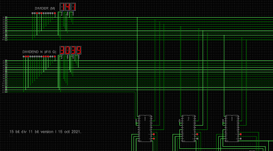
Here's an example of the divider in operation. The input is 3039 (hex) ÷ 141 (hex)...
...and the output is 26 (hex), remainder 93 (hex):
Cool huh?!
Some further examples:
31 ÷ A = 4, remainder 9
5565 ÷ 4AA = 12, remainder 171
7FFF ÷ 7FF = 10, remainder F
Chip count:
48 × 74181-bit slice arithmetic logic unit
16 × 74182 look-ahead carry generator
6 × 7404 hex inverter
[1] J.E. Robertson, "A new class of digital division methods," IRE Trans, of Elec. Comp., Vol. EC-7, No.3 (Sept. 1958), pp. 218-222.
[2] Daniel E. Atkins, “HIGHER RADIX, NON-RESTORING DIVISION: HISTORY AND RECENT DEVELOPMENTS”, Computer Arithmetic (ARITH), IEEE 3rd Symposium, pp. 158-160, 1975.