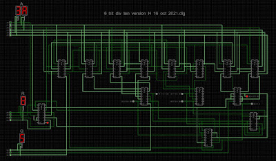
This is the easiest of the two divisions needed in the spigot algorithm: we have the division of a six bit number (d in the spigot algorithm) by the decimal value ten (i.e. 1010); both quotient and remainder are required.
My solution
Observation: the dividend (A) ranges from 000000 to 111111; 0 through 63 (3F hex), and so, by inspection the quotient (Q) can only take one of seven values: 0, 1, 2, 3, 4, 5 or 6. That is (all numbers decimal):
A < 10 ⟶ Q = 0
10 ≤ A < 20 ⟶ Q = 1
20 ≤ A < 30 ⟶ Q = 2
30 ≤ A < 40 ⟶ Q = 3
40 ≤ A < 50 ⟶ Q = 4
50 ≤ A < 60 ⟶ Q = 5
60 ≤ A ⟶ Q = 6
So, the game is to determine which of the above ranges the dividend (A) falls into - this immediately gives the quotient, Q. The remainder (R) is then found by multiplying the quotient by ten and subtracting the result from the original dividend (A).
Hence, if 30 ≤ A < 40, we need to subtract 30 (i.e. 011110) from the dividend to get the remainder. And so on, like this:
A < 10 ⟶ Q = 0; subtract 000000
10 ≤ A < 20 ⟶ Q = 1; subtract 001010
20 ≤ A < 30 ⟶ Q = 2; subtract 010100
30 ≤ A < 40 ⟶ Q = 3; subtract 011110
40 ≤ A < 50 ⟶ Q = 4; subtract 101000
50 ≤ A < 60 ⟶ Q = 5; subtract 110010
60 ≤ A ⟶ Q = 6; subtract 111100
In my first attempt, the above inequalities were determined using 7485 4-bit magnitude comparators (12 off), plus some logic. This seemed an obvious enough approach.
A 74283 4-bit binary full adder dispatches the subtraction of ten times Q from A, giving the remainder, the ten times Q part being realised with some straightforward logic (7427 triple 3-input NOR and 7425 dual 4-input NOR) to decode the Q = 1 through Q = 6 cases into the required subtrahend (e.g. 011110 when Q = 3). This logic actually gives the inverted version of the number to be subtracted (since the 74283 is an adder); the 7404 inverts what's needed for the 3 bits of the quotient Q.
Here's the circuit:
A refinement
An analysis of the above circuit - which is easy enough to do in Helmut Neemann's Digital logic simulator (i.e. press F9) - gives the following Boolean expressions:
This shows that the twelve 4-bit magnitude comparator solution is a bit of a sledgehammer; the above Boolean expressions can be realised rather more concisely with:
5 off 7420 dual 4-input NAND
3 off 7410 triple 3-input NAND
1 off 74260 dual 5-input NOR
1 off 7411 triple 3-input AND
1 off 7432 quad 2-input OR
1 off 7404 hex inverter
That's a reduction of six chips, plus it's a nicely esoteric selection of 1,2,3,4 and 5 input gates! Note that the 5-input NOR gates are used to implement the 5-input ANDs needed for rows 3 and 4 of the above Boolean expressions, negated versions of the inputs being used to realise the logical AND from the NOR; there isn't a 5-input AND in 74 series TTL. In fact, the 74260 is (I think) the only 5-input gate available in TTL.
Here's the final circuit:
The 7404 hex inverter from the first iteration (needed to invert the 3 bits of quotient Q) has gone; the two 7410 chips each had a spare NAND gate, as did the 7404 chip (used to invert five of the six the bits of the dividend A). The refined approach needs fifteen chips, versus the 22 of the original approach.
The activated final circuit looks like this:
Here the input (dividend, A) is 3A or 58 decimal; the quotient is 5, and the remainder is 8, the correct answer since 5 × 10 + 8 = 58 (decimal) . The seven LEDs are included for diagnostics: the illuminated LED indicates that 50 ≤ A < 60, which is indeed the case.
Some further examples:
31 ÷ A = 4, remainder 9
3F ÷ A = 6, remainder 3
1E ÷ A = 3, remainder 0
Chip count:
5 × 7420 dual 4-input NAND
3 × 7410 triple 3-input NAND
1 × 74260 dual 5-input NOR
1 × 7411 triple 3-input AND
1 × 7432 quad 2-input OR
1 × 7404 hex inverter
1 × 7427 triple 3-input NOR
1 × 7425 dual 4-input NOR
1 × 74283 4-bit binary full adder


