The complete set of schematics can be found here:
https://github.com/pac-mcnair/spigot-machine
(.dig (Digital) files, .svg files and PDFs)
The complete set of schematics can be found here:
https://github.com/pac-mcnair/spigot-machine
(.dig (Digital) files, .svg files and PDFs)
Setting GAMMA = 1, BETA = 10, ALPHA = -1 and omitting the d = d * b operation (OP#1), the machine pops out:


...and so on. The first 2,232 digits are correct, as far as the 369. Then we get 975; the correct digits are 882.

The machine has a counter that displays the total number of triplets output - for the above, the count is 745 = 2235 digits have been output.

It's not that fast: the Digital simulation took about five hours(!) to get to triplet number 745. When the simulation's running, there's a little '3 kHz' at the bottom left of the Digital screen - not sure what this means/indicates...but it'll be interesting to see how fast/slow the actual circuitry is in practice.
This is the top level circuitry, which implements the loop structure of the algorithm, and holds the various variables. It also deals with user control - i.e. the user can reset, run, pause etc the computation. And, there's the important matter of output. The top level circuitry makes use of the various previously-described sub-circuits:
[master loop version Z 19 feb 2022.dig]
The 15 bit div 11 bit circuit (posted November 2021) is unchanged, but had to be re-drawn - to make it readable when printed even on the biggest available paper size! The 15 bit div 11 bit 'blocked' version divides the original circuit into five stages, each of which is implemented as a '15 bit div 11 triple block' circuit (which contains nine 74181 ALUs).
The complete master loop circuit is shown below - it's pretty much unreadable as it stands, so it's been divided into ten pieces.

The various pieces are interconnected with Digital 'tunnel elements'; in real life these will be interconnecting wires (ribbon cable?). Each of the ten pieces is a reasonable size (chip count) to go on a single board; so about ten boards for the master loop, plus three further boards, plus the 15 bit div 11 which is likely to be six boards in itself, giving something like 19 boards in total. I am thinking about 100 mm x 220 mm Eurocard types.
Anyway, here's the output (appearing at the bottom right (block 10)) of the master loop circuit - the circuit displays eighteen digits at a time; the left-hand nine digits are:

and the right-hand nine digits are:

And, yes, that's a decimal point after the first digit. In operation, the digits pop out in groups of three, and the display scrolls across (with said decimal point). The user has the option of making the machine wait after it has output eighteen digits; pressing RESUME, starts the calculation of the next batch of 18 digits (the final triplet is shown also):

[I've also included some circuitry to interface to a 3-digit printer(!) - this allows a printer to tell the machine to wait, whilst it prints out the triplet of digits (perhaps some sort of wood block contraption printing onto a long roll of paper would be fun...)].
I'll put more detail of each of the ten pieces of the master loop circuit in the next few posts.
plus LEDs for diagnostics, and for output of the eighteen digits of the number - at least at the moment. Maybe I'll go for a vacuum fluorescent display of Nixie tubes.
The total chip count (i.e. including all sub-circuits) stands at 358. Perhaps appropriately for a machine of this nature, the most numerous chip is the 74181 ALU (55 required); the next most popular is the 7408 quad 2-input AND (39), followed by the 74367 hex non-inverting buffer - to drive diagnostic LEDs (38).
Thinking ahead, I guess something like 20 - 30 amps might be needed...
Here's the 10 bit x 3 bit multiply circuit - it's just a cut down version of the previously-posted 10 bit x 6 bit multiplier:

6 × 74283 (4-bit full adder)
8 × 7408 (quad AND gate)
plus LEDs for diagnostics.
I've revisited the spigot algorithm (posted 25th September 2021), and in the spirit of exploration, looked at what happens if:
(a) d = d + 20 becomes d = d + BETA, where BETA is an integer;
(b) g = 2 * b - 1 becomes g = GAMMA * b ± ALPHA, where GAMMA and ALPHA are integers;
(c) d = d * b becomes optional.
These changes are interesting because they are easily implemented in the hardware, and enable numbers other than π to be computed. The first 'discovery' was:
ALPHA = 0, BETA = 10 and GAMMA = 1, with operation d = d * b omitted, which yields 🥁🥁🥁
1.718281828459045235360287471352662497757247093699959574966967627724076...
which is one less than Euler's number.
Or, how about ALPHA = -1, BETA = 10 and GAMMA = 1, with operation d = d * b omitted?
2.718281828459045235360287471352662497757247093699959574966967627724076...
which is Euler's number. Interestingly, the algorithm produces (and thus the TTL implementation should produce) an amazing 2,235 correct digits of e.
So, the project, which started as a challenge to compute π has morphed into computing π, e, and other constants; it's something of a game to figure out what the constant is that's been computed - for a given ALPHA, BETA and GAMMA (with d = d * b included or omitted). More on this later.
Here's the revised algorithm:

Changing g = 2 * b - 1 to g = GAMMA * b ± ALPHA means some additional hardware to multiply a ten bit number (b) by GAMMA. To keep things reasonable, GAMMA is limited to a 3 bit value, i.e. GAMMA can range from 0 through 7. This needs a 10 bit times 3 bit multiplier...
Required: quotient and remainder of a fifteen bit number divided by an eleven bit number. This is for the third boxed part of the algorithm:

where d is 15 bits and g 11 bits. The maximum possible value for the remainder is 2046 (7FE hex), which occurs for the case 2046 % 2047 (decimal). Since 2046 is 11111111110 in binary, we need to accommodate an 11-bit remainder.
Similarly, the maximum possible value for the quotient is 32767 (7FFF hex), which occurs for the case 32767 / 1, and since 32767 is 111111111111111 in binary, we need to accommodate a 15-bit quotient.
This approach seems attractive [1,2]. An important point to note is that 'left shift A,Q' means that the most significant bit of Q replaces the least significant bit of A. Here's a flow chart:




Some further examples:
31 ÷ A = 4, remainder 9
5565 ÷ 4AA = 12, remainder 171
7FFF ÷ 7FF = 10, remainder F
48 × 74181-bit slice arithmetic logic unit
16 × 74182 look-ahead carry generator
6 × 7404 hex inverter
[1] J.E. Robertson, "A new class of digital division methods," IRE Trans, of Elec. Comp., Vol. EC-7, No.3 (Sept. 1958), pp. 218-222.
[2] Daniel E. Atkins, “HIGHER RADIX, NON-RESTORING DIVISION: HISTORY AND RECENT DEVELOPMENTS”, Computer Arithmetic (ARITH), IEEE 3rd Symposium, pp. 158-160, 1975.
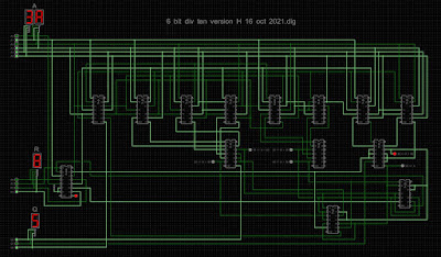
This is the easiest of the two divisions needed in the spigot algorithm: we have the division of a six bit number (d in the spigot algorithm) by the decimal value ten (i.e. 1010); both quotient and remainder are required.
Observation: the dividend (A) ranges from 000000 to 111111; 0 through 63 (3F hex), and so, by inspection the quotient (Q) can only take one of seven values: 0, 1, 2, 3, 4, 5 or 6. That is (all numbers decimal):
A < 10 ⟶ Q = 0
10 ≤ A < 20 ⟶ Q = 1
20 ≤ A < 30 ⟶ Q = 2
30 ≤ A < 40 ⟶ Q = 3
40 ≤ A < 50 ⟶ Q = 4
50 ≤ A < 60 ⟶ Q = 5
60 ≤ A ⟶ Q = 6
So, the game is to determine which of the above ranges the dividend (A) falls into - this immediately gives the quotient, Q. The remainder (R) is then found by multiplying the quotient by ten and subtracting the result from the original dividend (A).
Hence, if 30 ≤ A < 40, we need to subtract 30 (i.e. 011110) from the dividend to get the remainder. And so on, like this:
A < 10 ⟶ Q = 0; subtract 000000
10 ≤ A < 20 ⟶ Q = 1; subtract 001010
20 ≤ A < 30 ⟶ Q = 2; subtract 010100
30 ≤ A < 40 ⟶ Q = 3; subtract 011110
40 ≤ A < 50 ⟶ Q = 4; subtract 101000
50 ≤ A < 60 ⟶ Q = 5; subtract 110010
60 ≤ A ⟶ Q = 6; subtract 111100
In my first attempt, the above inequalities were determined using 7485 4-bit magnitude comparators (12 off), plus some logic. This seemed an obvious enough approach.
A 74283 4-bit binary full adder dispatches the subtraction of ten times Q from A, giving the remainder, the ten times Q part being realised with some straightforward logic (7427 triple 3-input NOR and 7425 dual 4-input NOR) to decode the Q = 1 through Q = 6 cases into the required subtrahend (e.g. 011110 when Q = 3). This logic actually gives the inverted version of the number to be subtracted (since the 74283 is an adder); the 7404 inverts what's needed for the 3 bits of the quotient Q.
Here's the circuit:

An analysis of the above circuit - which is easy enough to do in Helmut Neemann's Digital logic simulator (i.e. press F9) - gives the following Boolean expressions:

This shows that the twelve 4-bit magnitude comparator solution is a bit of a sledgehammer; the above Boolean expressions can be realised rather more concisely with:
5 off 7420 dual 4-input NAND
3 off 7410 triple 3-input NAND
1 off 74260 dual 5-input NOR
1 off 7411 triple 3-input AND
1 off 7432 quad 2-input OR
1 off 7404 hex inverter
That's a reduction of six chips, plus it's a nicely esoteric selection of 1,2,3,4 and 5 input gates! Note that the 5-input NOR gates are used to implement the 5-input ANDs needed for rows 3 and 4 of the above Boolean expressions, negated versions of the inputs being used to realise the logical AND from the NOR; there isn't a 5-input AND in 74 series TTL. In fact, the 74260 is (I think) the only 5-input gate available in TTL.
Here's the final circuit:

The 7404 hex inverter from the first iteration (needed to invert the 3 bits of quotient Q) has gone; the two 7410 chips each had a spare NAND gate, as did the 7404 chip (used to invert five of the six the bits of the dividend A). The refined approach needs fifteen chips, versus the 22 of the original approach.
The activated final circuit looks like this:
Here the input (dividend, A) is 3A or 58 decimal; the quotient is 5, and the remainder is 8, the correct answer since 5 × 10 + 8 = 58 (decimal) . The seven LEDs are included for diagnostics: the illuminated LED indicates that 50 ≤ A < 60, which is indeed the case.
Some further examples:
31 ÷ A = 4, remainder 9
3F ÷ A = 6, remainder 3
1E ÷ A = 3, remainder 0
5 × 7420 dual 4-input NAND
3 × 7410 triple 3-input NAND
1 × 74260 dual 5-input NOR
1 × 7411 triple 3-input AND
1 × 7432 quad 2-input OR
1 × 7404 hex inverter
1 × 7427 triple 3-input NOR
1 × 7425 dual 4-input NOR
1 × 74283 4-bit binary full adder
The second multiplication that occurs in the spigot algorithm is that of an eleven bit number (g) by the decimal value ten (i.e. 1010, hex A).
A pragmatic place to start is with the previously described 10 bit × 6 bit multiplier; the six bits of the multiplier being set to 001010, with an eleventh bit added to the multiplicand.
The fact that we are multiplying by a constant (1010) leads to some considerable simplifications; in the first place, all the AND gates can go. The game continues with removing all the circuitry that doesn't do anything. This quickly reduced the thing to just 4 off 74283 4-bit full adder chips.
(One 'trick' that proved useful is to hook up the 11-bit input to an 11-bit counter circuit (3 off 74163 binary counters), and see which lines remain at logic zero (or one), as the counter clocks, and then remove the same.)
In fact, it proves possible to reduce the chip count to just three 74283 chips: after some thought it's apparent that the lower 74283 chip (see circuit below) can do two things: (1) generate bits 12 - 14 of the product, and (2) generate bit P3 of the product and the carry bit that is needed by what is now the uppermost 74283. We can get away with this because inputs A3 and B3 to the lower 74283 are always zero; whatever happens in the lower part of this adder (i.e. inputs A1, A2, B1, B2) cannot affect the A4, B4 part of the adder (i.e. adder outputs S4 and C4). Cool huh?!
Here's the final 11 bit × ten multiply circuit:

Pressing the space bar activates the circuit in Digital:

Here the input (multiplicand, B) is 7FF or 2047 decimal; the output is 4FF6 or 20470 decimal, the correct answer! The three LEDs, which are the carry outputs from the adders, are included for diagnostics.
Some further examples:
317 × A = 1EE6
754 × A = 4948
001 × A = 000A
007 × A = 0046
In the final circuit, the lowest significant bit of the product (P0) is connected to ground - it's always zero. The next two bits of the product are also straightforward, given by P1= B0 and P2= B1.
This makes sense: since multiplying a number by ten is the same as multiplying the number by 2 and then by 5, it is evident that the lowest significant bit of the product will always be zero; multiplication by 2 being a left shift. The fact that next two bits, P1 and P2, are given by B1 and B2 is clear from the following example. The right-most three digits of the second row, formed by a shift of the multiplicand (11111111111), have nothing added to them - the row above is zero and the row below is zero; the right-most three digits of the fourth row are also (always) zero, hence the boxed digits appear in the product.

3 × 74283 (4-bit full adder)
So here we have it...the 10 bit times 6 bit multiplier, put together using Helmut Neemann's excellent Digital - simulator for digital circuits:
https://github.com/hneemann/Digital
It's got an excellent in library of 74-series chips. Speaking of which:
17 × 74283 (4-bit full adder)
15 × 7408 (quad AND gate)
plus LEDs (to show amongst other things the partial sums in binary) and the aforementioned TIL311 hexadecimal displays (to show A, B and A × B) - although not strictly needed, these will prove invaluable if/when I get around to real chips and real solder and real mistakes.

And this is what happens when you switch it on (i.e. press the space bar in Digital). The two inputs (upper left) are A = 3F (111111) and B = 3FF (1111111111) and the product (lower left) is FbC1, which is the correct answer 😌.

the sum of these giving the product, 64449 decimal or FbC1.
The intermediate quantity, U = R + S = 0101111111101 + 010111111110100 = 011101111110001, is shown by the lower left row of LEDs.
Some further examples:
3F × 001 = 003F
2A × 2AA = 6FE4
00 × 392 = 0000
34 × 3B3 = C05C
2d × 3b5 = 36d1
So, we need to multiply a 6-bit number (d) by a 10-bit number (b). Like this:

Writing the thing out as a grade-school (i.e. long) multiplication shows what seems like a reasonable approach. Each bit of the ten bit number (multiplicand) is multiplied by the first (right-most) bit of the six bit number (multiplier); this forms the first row - partial product PP0. Next, each bit of the multiplicand is multiplied by the second bit of the multiplier; this forms the second row. This row is shifted one place to the left. This row is partial product PP1. And so on.
We then add together the six partial products, the sum being the product of the two original numbers.
The numbers in red are hexadecimal, those in blue decimal: 1023× 63 = 64449. Hex is easier to read (at least for me!) than binary; I can use 1970s era TIL311 LED hexadecimal displays from Texas Instruments in actual circuitry. At least for intermediate results: the final digits of π will, of course, be decimal 😃.
Multiplication by a single bit is easy enough - an AND gate. To get all six partial products needs sixty gates (that's fifteen 7408 chips). The partial products then get added together with 74283 chips (4-bit binary full adders). We add together PP0 + PP1 to get R, then similarly S and T then need to add R + S = U and finally U + T, to give the product. That's seventeen 7283 chips in total; the 4-bit adders need cascading in groups of 3 or 4 so as to add together numbers with more than four bits, for example adding together PP0 (10 bits) and PP1 (11 bits) needs 3× 4-bit chips, to give the (potentially) 12-bit result (101111111101, as for the example above).

Here's the output produced by the spigot algorithm shown in the previous post. Digits are output in groups of three, hence the arrangement shown - the π digits are in the rectangular boxes. The first 263 digits are correct; the 264th digit is incorrect (it should be a six). The decimal point has been added manually.

There's an elegant method for calculating certain transcendental numbers (like π, e) called a spigot algorithm; "spigot" as in a tap or valve controlling the flow of a liquid (or perhaps a gas?); such an algorithm for calculating the digits of e appeared in a paper by Sale in 1968 [1].
Spigot algorithms work with 'nice small integers' and start producing digits (of π in our case) right from the start [2,3], and so seems a good basis for the Transcendental Logic Circuit...
The following algorithm - which will form the heart of the Transcendental Logic Circuit - is a modification of the C spigot program given by Arndt and Haenel [2, p. 83], the aim being to make the thing work with integers that use 15 or fewer bits, producing (at least) 256 digits of π. The colour coding indicates the required size for each variable:
grey 2 bits
violet 4 bits
green 6 bits
blue 10 bits
orange 11 bits
brown 14 bits
red 15 bits
This level of bit-fastidiousness is not unimportant - unnecessary bits can have dramatic effects on the complexity of the hardware!

[1] A. H. J. Sale, The calculation of e to many significant digits, Comput. J. 11 (1968), pp. 229–230.
[2] Jörg Arndt, Christoph Haenel, Pi - Unleashed, Springer-Verlag Berlin, 2nd. ed., 2001, chap. 6.
[3] Stanley Rabinowitz and Stan Wagon, A Spigot Algorithm for the Digits of π, Am. Math. Monthly., Vol. 102, No. 3 (Mar., 1995), pp. 195-203.
